There are many reasons such as noise, cross-talk etc., which may help
data to get corrupted during transmission. The upper layers works on
some generalized view of network architecture and are not aware of
actual hardware data processing. So, upper layers expect error-free
transmission between systems. Most of the applications would not
function expectedly if they receives erroneous data. Applications such
as voice and video may not be that affected and with some errors they
may still function well.
Data-link layer uses some error control mechanism to ensure that
frames (data bit streams) are transmitted with certain level of
accuracy. But to understand how errors is controlled, it is essential
to know what types of errors may occur.
There may be three types of errors:
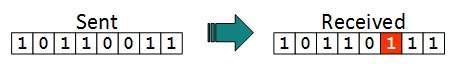
Single bit error: [Image: Single bit error]
In a frame, there is only one bit, anywhere though, which is corrupt.
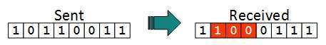
Multiple bits error: [Image: Multiple bits error]
Frame is received with more than one bits in corrupted state.
Error control mechanism may involve two possible ways:
Error detection
Error correction
Error Detection
Errors in the received frames are detected by means of Parity Check
and CRC (Cyclic Redundancy Check). In both scenario, few extra bits are
sent along with actual data to confirm that bits received at other end
are same as they were sent. If the checks at receiver’s end fails, the
bits are corrupted.
Parity Check
One extra bit is sent along with the original bits to make number of
1s either even, in case of even parity or odd, in case of odd parity.
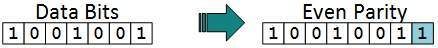
The sender while creating a frame counts the number of 1s in it, for
example, if even parity is used and number of 1s is even then one bit
with value 0 is added. This way number of 1s remain even. Or if the
number of 1s is odd, to make it even a bit with value 1 is added. [Image: Even Parity]
The receiver simply counts the number of 1s in a frame. If the count
of 1s is even and even parity is used, the frame is considered to be
not-corrupted and is accepted. If the count of 1s is odd and odd parity
is used, the frame is still not corrupted.
If a single bit flips in transit, the receiver can detect it by
counting the number of 1s. But when more than one bits are in error it
is very hard for the receiver to detect the error
Cyclic Redundancy Check
CRC is a different approach to detect if the frame received contains
valid data. This technique involves binary division of the data bits
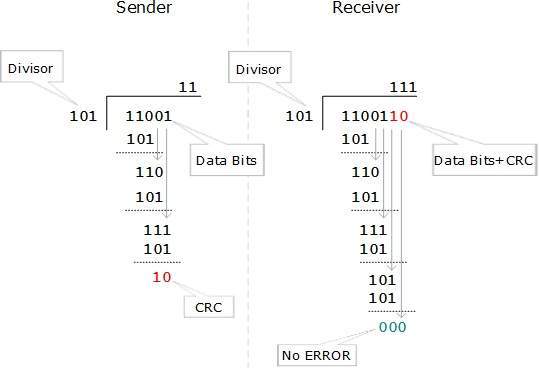
being sent. The divisor is generated using polynomials. The sender
performs a division operation on the bits being sent and calculates the
remainder. Before sending the actual bits, the sender adds the
remainder at the end of the actual bits. Actual data bits plus the
remainder is called a codeword. The sender transmits data bits as
codewords. [Image: CRC in action]
At the other end, the receiver performs division operation on
codewords using the same CRC divisor. If the remainder contains all
zeros the data bits are accepted, otherwise there has been some data
corruption occurred in transit.
Error Correction
In digital world, error correction can be done in two ways:
Backward Error Correction: When the receiver detects an error in the data received, it requests back the sender to retransmit the data unit.
Forward Error Correction: When the receiver detects some
error in the data received, it uses an error-correcting code, which
helps it to auto-recover and correct some kinds of errors.
The first one, Backward Error Correction, is simple and can only be
efficiently used where retransmitting is not expensive, for example
fiber optics. But in case of wireless transmission retransmitting may
cost too much. In the latter case, Forward Error Correction is used.
To correct the error in data frame, the receiver must know which bit
(location of the bit in the frame) is corrupted. To locate the bit in
error, redundant bits are used as parity bits for error detection. If
for example, we take ASCII words (7 bits data), then there could be 8
kind of information we need. Up to seven information to tell us which
bit is in error and one more to tell that there is no error.
For m data bits, r redundant bits are used. r bits can provide 2r
combinations of information. In m+r bit codeword, there is possibility
that the r bits themselves may get corrupted. So the number of r bits
used must inform about m+r bit locations plus no-error information, i.e.
m+r+1.

No comments:
Post a Comment