Data-link layer is responsible for implementation of point-to-point flow and error control mechanism.
Flow Control
When data frames (Layer-2 data) is sent from one host to another over
a single medium, it is required that the sender and receiver should
work on same speed. That is, sender sends at a speed on which the
receiver can process and accept the data. What if the speed
(hardware/software) of the sender or receiver differs? If sender is
sending too fast the receiver may be overloaded (swamped) and data may
loss.
Two types of mechanism can be deployed in the scenario to control the flow:
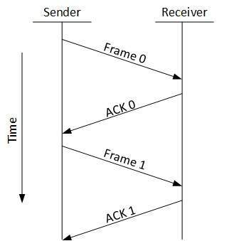
Stop and Wait
This flow control mechanism forces the sender after transmitting a
data frame to stop and wait until the acknowledgement of the data-frame
sent is received.
[Image: Stop and Wait Protocol]
Sliding Window
In this flow control mechanism both sender and receiver agrees on the
number of data-frames after which the acknowledgement should be sent.
As we have seen, stop and wait flow control mechanism wastes resources,
this protocol tries to make use of underlying resources as much as
possible.
Error Control
When data-frame is transmitted there are probabilities that
data-frame may be lost in the transit or it is received corrupted. In
both scenarios, the receiver does not receive the correct data-frame and
sender does not know anything about any loss. In these types of cases,
both sender and receiver are equipped with some protocols which helps
them to detect transit errors like data-frame lost. So, either the
sender retransmits the data-frame or the receiver may request to repeat
the previous data-frame.
Requirements for error control mechanism:
Error detection: The sender and receiver, either both or any, must ascertain that there’s been some error on transit.
Positive ACK: When the receiver receives a correct frame, it should acknowledge it.
Negative ACK: When the receiver receives a damaged frame
or a duplicate frame, it sends a NACK back to the sender and the sender
must retransmit the correct frame.
Retransmission: The sender maintains a clock and sets a
timeout period. If an acknowledgement of a data-frame previously
transmitted does not arrive in the timeout period, the sender retransmit
the frame, thinking that the frame or it’s acknowledge is lost in
transit.
There are three types of techniques available which Data-link layer
may deploy to control the errors by Automatic Repeat Requests (ARQ):
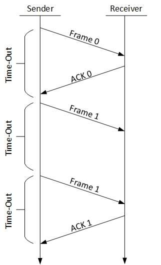
Stop-and-wait ARQ
[Image: Stop and Wait ARQ]
The following transition may occur in Stop-and-Wait ARQ:
The sender maintains a timeout counter.
When a frame is sent the sender starts the timeout counter.
If acknowledgement of frame comes in time, the sender transmits the next frame in queue.
If acknowledgement does not come in time, the sender assumes that
either the frame or its acknowledgement is lost in transit. Sender
retransmits the frame and starts the timeout counter.
If a negative acknowledgement is received, the sender retransmits the frame.
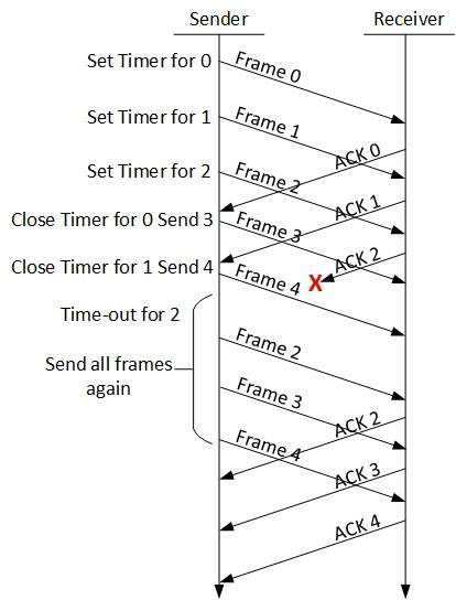
Go-Back-N ARQ
Stop and wait ARQ mechanism does not utilize the resources at their
best. For the acknowledgement is received, the sender sits idle and
does nothing. In Go-Back-N ARQ method, both sender and receiver
maintains a window. [Image: Go-Back-N ARQ]
The sending-window size enables the sender to send multiple frames
without receiving the acknowledgement of the previous ones. The
receiving-window enables the receiver to receive multiple frames and
acknowledge them. The receiver keeps track of incoming frame’s sequence
number.
When the sender sends all the frames in window, it checks up to what
sequence number it has received positive ACK. If all frames are
positively acknowledged, the sender sends next set of frames. If sender
finds that it has received NACK or has not receive any ACK for a
particular frame, it retransmits all the frames after which it does not
receive any positive ACK.
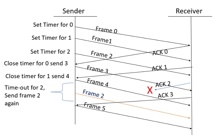
Selective Repeat ARQ
In Go-back-N ARQ, it is assumed that the receiver does not have any
buffer space for its window size and has to process each frame as it
comes. This enforces the sender to retransmit all the frames which are
not acknowledged. [Image: Selective Repeat ARQ]
In Selective-Repeat ARQ, the receiver while keeping track of sequence
numbers, buffers the frames in memory and sends NACK for only frame
which is missing or damaged.
The sender in this case, sends only packet for which NACK is received.
There are many reasons such as noise, cross-talk etc., which may help
data to get corrupted during transmission. The upper layers works on
some generalized view of network architecture and are not aware of
actual hardware data processing. So, upper layers expect error-free
transmission between systems. Most of the applications would not
function expectedly if they receives erroneous data. Applications such
as voice and video may not be that affected and with some errors they
may still function well.
Data-link layer uses some error control mechanism to ensure that
frames (data bit streams) are transmitted with certain level of
accuracy. But to understand how errors is controlled, it is essential
to know what types of errors may occur.
There may be three types of errors:
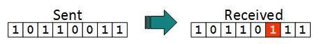
Single bit error: [Image: Single bit error]
In a frame, there is only one bit, anywhere though, which is corrupt.
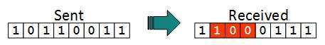
Multiple bits error: [Image: Multiple bits error]
Frame is received with more than one bits in corrupted state.
Error control mechanism may involve two possible ways:
Error detection
Error correction
Error Detection
Errors in the received frames are detected by means of Parity Check
and CRC (Cyclic Redundancy Check). In both scenario, few extra bits are
sent along with actual data to confirm that bits received at other end
are same as they were sent. If the checks at receiver’s end fails, the
bits are corrupted.
Parity Check
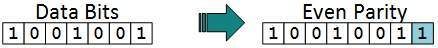
One extra bit is sent along with the original bits to make number of
1s either even, in case of even parity or odd, in case of odd parity.
The sender while creating a frame counts the number of 1s in it, for
example, if even parity is used and number of 1s is even then one bit
with value 0 is added. This way number of 1s remain even. Or if the
number of 1s is odd, to make it even a bit with value 1 is added. [Image: Even Parity]
The receiver simply counts the number of 1s in a frame. If the count
of 1s is even and even parity is used, the frame is considered to be
not-corrupted and is accepted. If the count of 1s is odd and odd parity
is used, the frame is still not corrupted.
If a single bit flips in transit, the receiver can detect it by
counting the number of 1s. But when more than one bits are in error it
is very hard for the receiver to detect the error
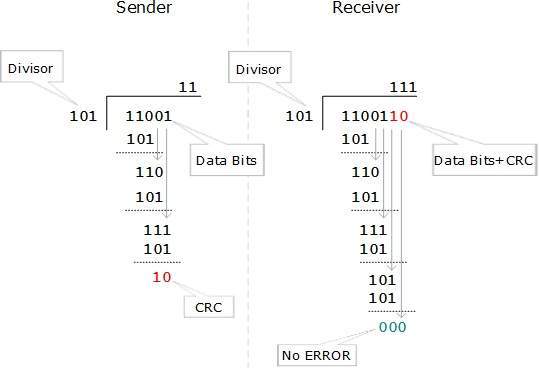
Cyclic Redundancy Check
CRC is a different approach to detect if the frame received contains
valid data. This technique involves binary division of the data bits
being sent. The divisor is generated using polynomials. The sender
performs a division operation on the bits being sent and calculates the
remainder. Before sending the actual bits, the sender adds the
remainder at the end of the actual bits. Actual data bits plus the
remainder is called a codeword. The sender transmits data bits as
codewords. [Image: CRC in action]
At the other end, the receiver performs division operation on
codewords using the same CRC divisor. If the remainder contains all
zeros the data bits are accepted, otherwise there has been some data
corruption occurred in transit.
Error Correction
In digital world, error correction can be done in two ways:
Backward Error Correction: When the receiver detects an error in the data received, it requests back the sender to retransmit the data unit.
Forward Error Correction: When the receiver detects some
error in the data received, it uses an error-correcting code, which
helps it to auto-recover and correct some kinds of errors.
The first one, Backward Error Correction, is simple and can only be
efficiently used where retransmitting is not expensive, for example
fiber optics. But in case of wireless transmission retransmitting may
cost too much. In the latter case, Forward Error Correction is used.
To correct the error in data frame, the receiver must know which bit
(location of the bit in the frame) is corrupted. To locate the bit in
error, redundant bits are used as parity bits for error detection. If
for example, we take ASCII words (7 bits data), then there could be 8
kind of information we need. Up to seven information to tell us which
bit is in error and one more to tell that there is no error.
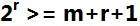
For m data bits, r redundant bits are used. r bits can provide 2r
combinations of information. In m+r bit codeword, there is possibility
that the r bits themselves may get corrupted. So the number of r bits
used must inform about m+r bit locations plus no-error information, i.e.
m+r+1.
Data Link Layer is second layer of OSI Layered Model. This layer is
one of the most complicated layers and has complex functionalities and
liabilities. Data link layers hides the details of underlying hardware
and represents itself to upper layer as the medium to communicate.
Data link layer works between two hosts which are directly connected
in some sense. This direct connection could be point to point or
broadcast. Systems on broadcast network are said to be on same link.
The work of data link layer tends to get more complex when it is dealing
with multiple hosts on single collision domain.
Data link layer is responsible for converting data stream to signals
bit by bit and to send that over the underlying hardware. At the
receiving end, Data link layer picks up data from hardware which are in
the form of electrical signals, assembles them in a recognizable frame
format, and hands over to upper layer.
Data link layer has two sub-layers:
Logical Link Control: Deals with protocols, flow-control and error control
Media Access Control: Deals with actual control of media
Functionality of Data-link Layer
Data link layer does many tasks on behalf of upper layer. These are:
Framing:
Data-link layer takes packets from Network Layer and encapsulates
them into Frames. Then, sends each Frame bit-by-bit on the hardware.
At receiver’s end Data link layer picks up signals from hardware and
assembles them into frames.
Addressing:
Data-link layer provides layer-2 hardware addressing mechanism.
Hardware address is assumed to be unique on the link. It is encoded
into hardware at the time of manufacturing.
Synchronization:
When data frames are sent on the link, both machines must be synchronized in order to transfer to take place.
Error Control:
Sometimes signals may have encountered problem in transition and bits
are flipped. These error are detected and attempted to recover actual
data bits. It also provides error reporting mechanism to the sender.
Flow Control:
Stations on same link may have different speed or capacity.
Data-link layer ensures flow control that enables both machine to
exchange data on same speed.
Multi-Access:
Hosts on shared link when tries to transfer data, has great
probability of collision. Data-link layer provides mechanism like
CSMA/CD to equip capability of accessing a shared media among multiple
Systems
Switching is process to forward packets coming in from one port to a
port leading towards the destination. When data comes on a port it is
called ingress, and when data leaves a port or goes out it is called
egress. A communication system may include number of switches and
nodes. At broad level, switching can be divided into two major
categories:
Connectionless: Data is forwarded on behalf of forwarding tables. No previous handshaking is required and acknowledgements are optional.
Connection Oriented: Before switching data to be
forwarded to destination, there is a need to pre-establish circuit along
the path between both endpoints. Data is then forwarded on that
circuit. After the transfer is completed, circuits can be kept for
future use or can be turned down immediately.
Circuit Switching
When two nodes communicates with each other over a dedicated
communication path, it is called circuit switching. There’s a need of
pre-specified route from which data will travel and no other data will
permitted. In simple words, in circuit switching, to transfer data
circuit must established so that the data transfer can take place.
Circuits can be permanent or temporary. Applications which use circuit switching may have to go through three phases:
Establish a circuit
Transfer of data
Disconnect the circuit
[Image: Circuit Switching]
Circuit switching was designed for voice applications. Telephone is
the best suitable example of circuit switching. Before a user can make a
call, a virtual path between caller and callee is established over the
network.
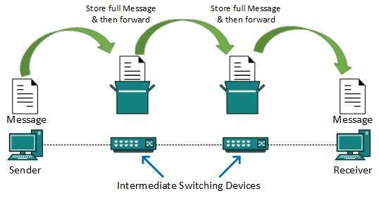
Message Switching
This technique was somewhere in middle of circuit switching and
packet switching. In message switching, the whole message is treated as
a data unit and is switching / transferred in its entirety.
A switch working on message switching, first receives the whole
message and buffers it until there are resources available to transfer
it to the next hop. If the next hop is not having enough resource to
accommodate large size message, the message is stored and switch waits. [Image: Message Switching]
This technique was considered substitute to circuit switching. As in
circuit switching the whole path is blocked for two entities only.
Message switching is replaced by packet switching. Message switching
has some drawbacks:
Every switch in transit path needs enough storage to accommodate entire message.
Because of store-and-forward technique and waits included until resources available, message switching is very slow.
Message switching was not a solution for streaming media and real-time applications.
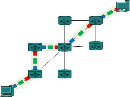
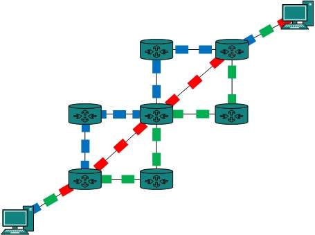
Packet Switching
Shortcomings of message switching gave birth to an idea of packet
switching. The entire message is broken down into smaller chunks called
packets. The switching information is added in the header of each
packet and transmitted independently.
It is easier for intermediate networking devices to store smaller
size packets and they do not take much resources either on carrier path
or in the switches’ internal memory. [Image: Packet Switching]
Packet switching enhances line efficiency as packets from multiple
applications can be multiplexed over the carrier. The internet uses
packet switching technique. Packet switching enables the user to
differentiate data streams based on priorities. Packets are stored and
forward according to their priority to provide Quality of Service.
Multiplexing is a technique by which different analog and digital
streams of transmission can be simultaneously processed over a shared
link. Multiplexing divides the high capacity medium into low capacity
logical medium which is then shared by different streams.
Communication is possible over the air (radio frequency), using a
physical media (cable) and light (optical fiber). All mediums are
capable of multiplexing.
When more than one senders tries to send over single medium, a device
called Multiplexer divides the physical channel and allocates one to
each. On the other end of communication, a De-multiplexer receives data
from a single medium and identifies each and send to different
receivers.
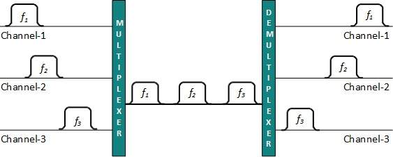
Frequency Division Multiplexing
When the carrier is frequency, FDM is used. FDM is an analog
technology. FDM divides the spectrum or carrier bandwidth in logical
channels and allocates one user to each channel. Each user can use the
channel frequency independently and has exclusive access of it. All
channels are divided such a way that they do not overlap with each
other. Channels are separated by guard bands. Guard band is a
frequency which is not used by either channel. [Image: Frequency Division Multiplexing]
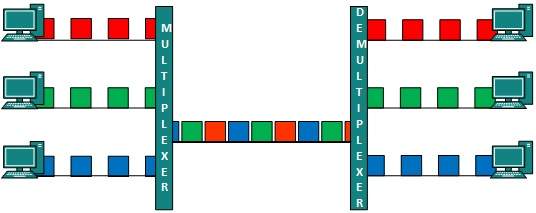
Time Division Multiplexing
TDM is applied primarily on digital signals but can be applied on
analog signals as well. In TDM the shared channel is divided among its
user by means of time slot. Each user can transmit data within the
provided time slot only. Digital signals are divided in frames,
equivalent to time slot i.e. frame of an optimal size which can be
transmitted in given time slot.
TDM works in synchronized mode. Both ends, i.e. Multiplexer and
De-multiplexer are timely synchronized and both switch to next channel
simultaneously. [Image: Time Division Multiplexing]
When at one side channel A is transmitting its frame, on the other
end De-multiplexer providing media to channel A. As soon as its channel
A’s time slot expires this side switches to channel B. On the other
end De-multiplexer behaves in a synchronized manner and provides media
to channel B. Signals from different channels travels the path in
interleaved manner.
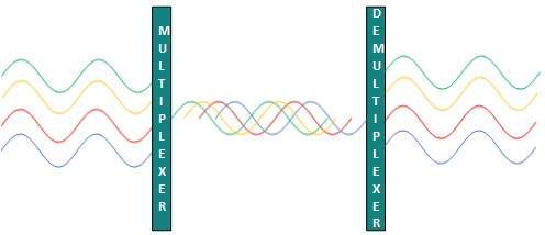
Wavelength Division Multiplexing
Light has different wavelength (colors). In fiber optic mode,
multiple optical carrier signals are multiplexed into on optical fiber
by using different wavelengths. This is an analog multiplexing
technique and is done conceptually in the same manner as FDM but uses
light as signals. [Image: Wavelength Division Multiplexing]
Further, on each wavelength Time division multiplexing can be incorporated to accommodate more data signals.
Code Division Multiplexing
Multiple data signals can be transmitted over a single frequency by
using Code Division Multiplexing. FDM divides the frequency in smaller
channels but CDM allows its users to full bandwidth and transmit signals
all the time using a unique Code. CDM uses orthogonal codes to spread
signals.
Each station is assigned with a unique code, called chip. Signals
travels with these codes independently travelling inside the whole
bandwidth. The receiver in this case, knows in advance chip code signal
it has to receive signals.
Wireless transmission is a form of unguided
media. Wireless communication involves no physical link established
between two or more devices, communicating wirelessly. Wireless signals
are spread over in the air and are received and interpret by
appropriate antennas.
When an antenna is attached to electrical circuit of a computer or
wireless device, it converts the digital data into wireless signals and
spread all over within its frequency range. The receptor on the other
end receives these signals and converts them back to digital data.
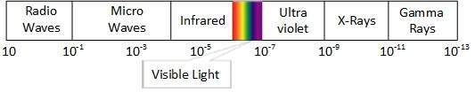
A little part of electromagnetic spectrum can be used for wireless transmission.
[Image: Electromagnetic Spectrum]
Radio Transmission
Radio frequency is easier to generate and because of its large
wavelength it can penetrate through walls and alike structures. Radio
waves can have wavelength from 1 mm – 100,000 km and have frequency
ranging from 3 Hz (Extremely Low Frequency) to 300 GHz (Extremely High
Frequency). Radio frequencies are sub-divided into six bands.
Radio waves at lower frequencies can travel through walls whereas
higher RF travel in straight line and bounces back. The power of low
frequency waves decreases sharply as it covers longer distance. High
frequency radio waves have more power.
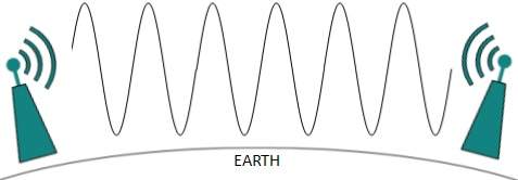
Lower frequencies like (VLF, LF, MF bands) can travel on the ground up to 1000 kilometers, over the earth’s surface.
[Image: Radio wave - grounded]
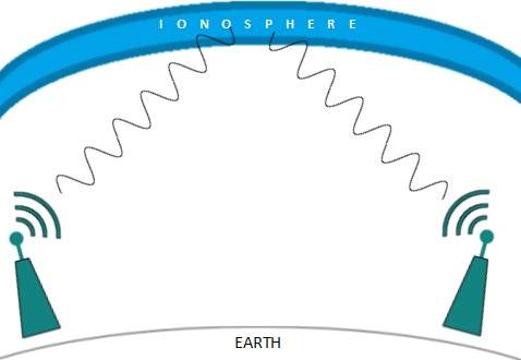
Radio waves on high frequencies are prone to be absorbed by rain and
other obstacles. They use Ionosphere of earth atmosphere. High
frequency radio waves such as HF and VHF bands are spread upwards. When
it reaches Ionosphere it is refracted back to the earth.
[Image: Radio wave - Ionosphere]
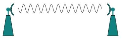
Microwave Transmission
Electromagnetic waves above 100 MHz tend to travel in a straight line
and signals over them can be sent by beaming those waves towards one
particular station. Because Microwaves travels in straight lines, both
sender and receiver must be aligned to be strictly in line-of-sight.
Microwaves can have wavelength ranging from 1 mm – 1 meter and frequency ranging from 300 MHz to 300 GHz.
[Image: Microwave Transmission]Microwave antennas concentrate the waves making a beam of
it. As shown in picture above multiple antennas can be aligned to reach
farther. Microwaves are higher frequencies and do not penetrate wall
like obstacles.
Microwaves transmission depends highly upon the weather conditions and the frequency it is using.
Infrared Transmission
Infrared waves lies in between visible
light spectrum and microwaves. It has wavelength of 700 nm to 1 mm and
frequency ranges from 300 GHz to 430 THz.
Infrared waves are used for very short range communication purposes
such as television and it’s remote. Infrared travels in a straight line
so they are directional by nature. Because of high frequency range,
Infrared do not cross wall like obstacles.
Light Transmission
Highest most electromagnetic spectrum which can be used for data
transmission is light or optical signaling. This is achieved by means
of LASER.
Because of frequency light uses, it tends to travel strictly in
straight line. So the sender and receiver must be in the line-of-sight.
Because laser transmission is unidirectional, at both ends of
communication laser and photo-detectors needs to be installed. Laser
beam is generally 1mm wide so it is a work of precision to align two far
receptors each pointing to lasers source.
[Image: Light Transmission]
Laser works as Tx (transmitter) and photo-detectors works as Rx (receiver).
Lasers cannot penetrate obstacles like walls, rain and thick fog.
Additionally, laser beam is distorted by wind and atmosphere temperature
or variation in temperature in the path.
Laser are safe for data transmission as it is very difficult to tap
1mm wide laser without interrupting the communication channel.
One of the most convenient way to transfer data from one computer to
another, even before the birth of networking, was to save it on some
storage media and transfer physical from one station to another. Though
it may seem odd in today’s world of high speed Internet, but when the
size of data to transfer is huge, Magnetic media comes into play.
For an example, say a Bank has Gigs of bytes of their customers’ data
which stores a backup copy of it at some geographically far place for
security and uncertain reasons like war or tsunami. If the Bank needs
to store its copy of data which is Hundreds of GBs, transfer through
Internet is not feasible way. Even WAN links may not support such high
speed or if they do cost will be too high to afford.
In these kinds of cases, data backup is stored onto magnetic tapes or
magnetic discs and then shifted physically at remote places.
Twisted Pair Cable
A twisted pair cable is made of two plastic insulated copper wires
twisted together to form a single media. Out of these two wires only
one carries actual signal and another is used for ground reference. The
twists between wires is helpful in reducing noise (electro-magnetic
interference) and crosstalk.
[Image: Twisted Pairs]
There are two types of twisted pair cables available:
Shielded Twisted Pair (STP) Cable
Unshielded Twisted Pair (UTP) Cable
STP cables comes with twisted wire pair covered in metal foil. This makes it more indifferent to noise and crosstalk.
UTP has seven categories, each suitable for specific use. In
computer networks, Cat-5, Cat-5e and Cat-6 cables are mostly used. UTP
cables are connected by RJ45 connectors.
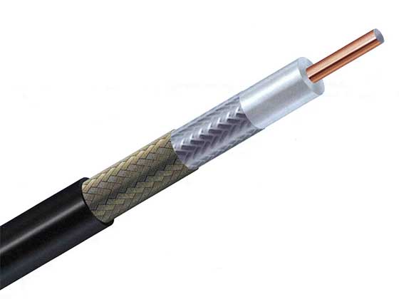
Coaxial Cable
Coaxial cables has two wires of copper. The core wire lies in center
and is made of solid conductor. Core is enclosed in an insulating
sheath. Over the sheath the second wire is wrapped around and that too
in turn encased by insulator sheath. This all is covered by plastic
cover.
[Image: Coaxial Cable]
Because of its structure coax cables are capable of carrying high
frequency signals than that of twisted pair cables. The wrapped
structure provides it a good shield against noise and cross talk.
Coaxial cables provide high bandwidth rates of up to 450 mbps.
There are three categories of Coax cables namely, RG-59 (Cable TV),
RG-58 (Thin Ethernet) and RG-11 (Thick Ethernet. RG stands for Radio
Government.
Cables are connected using BNC connector and BNC-T. BNC terminator is used to terminate the wire at the far ends.
Power Lines
Power Line communication is Layer-1 (Physical Layer) technology which
uses power cables to transmit data signals. Send in PLC modulates data
and sent over the cables. The receiver on the other end de-modulates
the data and interprets.
Because power lines are widely deployed, PLC can make all powered devices controlled and monitored. PLC works in half-duplex.
Two types of PLC exists:
Narrow band PLC
Broad band PLC
Narrow band PLC provides lower data rates up to 100s of kbps, as they
work at lower frequencies (3-5000 kHz). But can be spread over several
kilometers.
Broadband PLC provides higher data rates up to 100s of Mbps and works
at higher frequencies (1.8 – 250 MHz). But cannot be much extended as
Narrowband PLC.
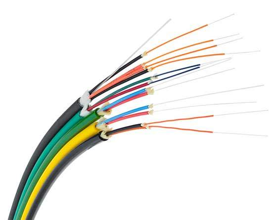
Fiber Optics
Fiber Optic works on the properties of light. When light ray hits at
critical angle it tends to refracts at 90 degree. This property has
been used in fiber optic. The core of fiber optic cable is made of high
quality glass or plastic. From one end of it light is emitted, it
travels through it and at the other end light detector detects light
stream and converts it to electric data form.
Fiber Optic provides the highest mode of speed. It comes in two
modes, one is single mode fiber and second is multimode fiber. Single
mode fiber can carries single ray of light whereas multimode is capable
of carrying multiple beams of light.
[Image: Fiber Optics]
Fiber Optic also comes in unidirectional and bidirectional
capabilities. To connect and access Fiber Optic special type of
connectors are used. These can be SC (Subscriber Channel), ST (Straight
Tip) or MT-RJ.